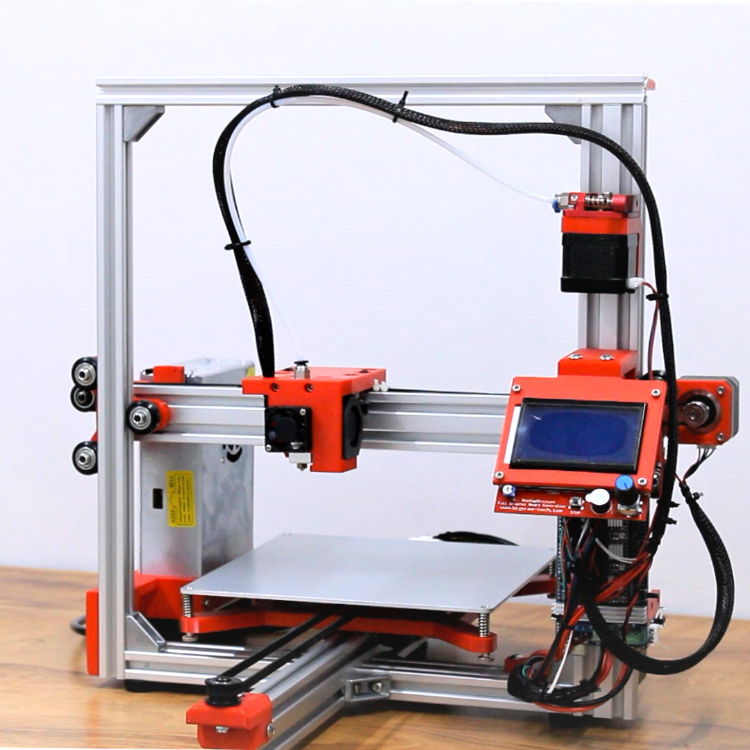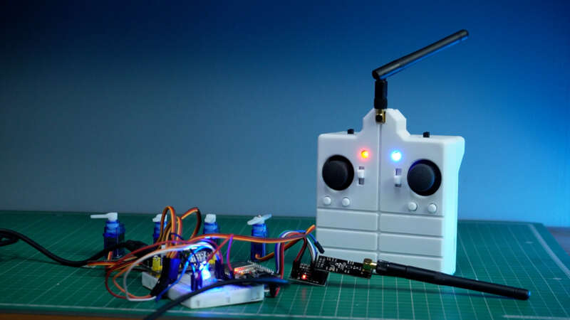
If you’re into RC projects and need a custom, multi-channel remote control, this guide is for you! In this project, I’ll walk you through building a versatile 8-channel ESP32 remote control using an ESP32 module. Packed with features like dual communication modes (ESP-NOW and NRF24L01), battery monitoring, and a sleek 3D-printed case, this remote is perfect for drones, cars, planes, or any RC application.
Features:
- ESP32 Remote control using 30-pin esp32 dev board
- 8 Channel control – 2 x Joysticks, 4 x Push Buttons, 2 x Toggle Switches
- NRF24l01 option for extended range
- built in lithium ion battery with low battery monitoring alert using LED
- 3D Printed case
Let’s dive in and build a professional-grade remote control that’s easy to replicate and customize!
Step 1: Gather the Parts

Start by gathering all necessary components. Here’s what you’ll need:v
- ESP32 30-pin module – https://bit.ly/esp32dev
- NRF24L01 module – https://bit.ly/nrf24l01ant
- 2 Joysticks – https://bit.ly/joystck
- 4 Push Buttons (19mm) – https://bit.ly/pushbt19mm
- TP4056 Step Up Module – https://bit.ly/tp4056stepup
- 3.7V 18650 Li-ion Battery – https://bit.ly/3ah18650
- 18650 Battery Holder – https://bit.ly/18650pcbholder
- Custom PCB (Download the GERBER file here) – comment below
- 3D-printed case (white color recommended for a clean aesthetic) –
- Miscellaneous parts: resistors, wires, headers, and soldering tools
BOM File link will be available soon for easy access to parts.
Step 2: Design and Order the PCB


Creating a custom PCB makes assembly easier, organizes components neatly, and gives the remote a professional finish.
I’ve already designed the PCB, so all you need to do is download the GERBER file, upload it to a PCB fabrication service, and wait a few days for your professionally made PCB to arrive. This custom board is essential for keeping the remote compact and durable.
Step 3: Soldering the Components

Once your PCB arrives, you can start soldering all components to the board:
- ESP32 and NRF24L01 Modules: Solder female headers so these modules are removable if needed.
- Joysticks, Buttons, and Switches: Place and solder these controls onto the PCB according to the layout.
- Battery Management Components: Solder the Battery Holder and TP4056 Step Up Module to the back of the PCB. This setup allows for USB-C charging and provides a consistent 5V output to power the ESP32.
Tip: Test each soldered connection with a multimeter to ensure proper conductivity and minimize troubleshooting later.
Step 4: Programming the ESP32

With the components in place, it’s time to program the ESP32. This remote has two operating modes:
- ESP-NOW Mode: Uses the ESP32’s built-in WiFi for communication, requiring only another ESP32 as a receiver. This mode has a range of up to 50 meters, ideal for short-range applications.
- NRF24L01 Mode: Uses the NRF24L01 antenna module to extend range to up to 500 meters, making it suitable for RC applications where a longer range is essential.
Code to Obtain MAC Address for ESP-NOW Mode
To use ESP-NOW, first obtain the MAC address of your receiver board with the following code:
#include
#include

void setup() {
  Serial.begin(115200);
  WiFi.mode(WIFI_STA);
  Serial.println(WiFi.macAddress());
}

void loop() {
  // Leave empty
}
With the MAC address ready, here’s sample code to send joystick and button data:
Remote Code
Step 5: 3D Printing the Case


Design a 3D-printed case that fits the PCB, buttons, switches, and joysticks perfectly. You can use software like Fusion 360 or Tinkercad to create the design, with precise cutouts for each component.
Once designed, print the case in white filament for a clean, professional appearance. After printing, test-fit all components to ensure the case fits snugly around the PCB and wiring.
i have already designed this case, you can download it from here:
Step 6: Testing the Remote Control


Once assembled, you’re ready to test the remote:
- Set Up Receiver: Use either an ESP32 or an NRF24L01-equipped receiver to test each channel.
- Verify Communication Modes: Toggle between ESP-NOW and NRF24L01 to ensure reliable data transmission.
- Battery Monitoring: Verify that the low-battery LED blinks when the battery voltage drops below the threshold.
Note: For additional range testing, perform outdoor trials to confirm the reach and stability of both communication modes.
Conclusion

This DIY 8-channel remote control is versatile, reliable, and tailored for RC hobbyists and DIY enthusiasts. With dual communication modes, battery monitoring, and a polished 3D-printed case, it’s ready for various RC applications.
Building this project on your own is a rewarding experience that adds a personal touch to any RC setup. Let me know how your remote turns out, and feel free to reach out with any questions or customizations you’d like to see!